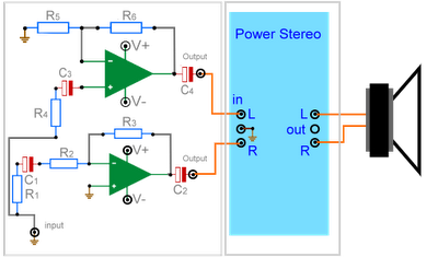
 R1, R2,R3, R4, R6 = 10kOhm
R3 = 20kOhm
C1, C2, C3, C4 = 10µF
V+ = 12V Dc( Catu daya simetris)
An amplifier circuit of a BTL system is disclosed, which comprises a first operational amplifier which outputs an output signal having a same phase as an input signal input to a signal input terminal, a second operational amplifier which outputs an output signal having an opposite phase to the input signal, a voltage divider which generates a midpoint voltage of the input signal, a first resistor connected between an output terminal and a negative phase input terminal of the first operational amplifier, second and third resistors connected in series between the negative phase input terminals of the first and second operational amplifiers, a fourth resistor connected between an output terminal and the negative phase input terminal of the second operational amplifier, and an impedance converter connected between a midpoint voltage node of the voltage divider and a series-connection node of the second and third resistors. (end of abstract)
Thursday, 23 July 2009
BTL for Sound System
Subscribe to:
Post Comments (Atom)

0 comments:
Post a Comment